
If you already have an existing account with another Cat App, you can use the same account to sign in here
One Account. All of Cat.
Your Caterpillar account is the single account you use to log in to select services and applications we offer. Shop for parts and machines online, manage your fleet, go mobile, and more.
Account Information
Site Settings
Security
Failsafe Operation for Load Sharing Paralleled Generator Sets
ABSTRACT
Failsafe Adaptive Load Sharing Operation (Failsafe Mode) ensures continued safe and stable operation, load sharing and load response after loss of a communication link.
Ed Schroeder
Caterpillar Electric Power
Ryan Byrd
Caterpillar Electric Power
Keith Folken
Caterpillar Electric Power
Josenia Gerdes
Caterpillar Electric Power
Amanda Wilke Diaz
Caterpillar Electric Power
October 2024
INTRODUCTION
In facilities with a high demand for power, such as a hospital or data center, communication among generator sets is crucial for maintaining power levels. In these types of applications, generator sets can be electrically connected to help manage the large power need. Called paralleling generator sets, this In facilities with a high demand for power, such as a hospital or data center, communication among generator sets is crucial for maintaining power levels. In these types of applications, generator sets can be electrically connected to help manage the large power need. Called paralleling generator sets, this configuration helps ensure more efficient load sharing and load response within a network.
One way to operate power systems with paralleled generator sets is to use dedicated multi-function engine generator set controllers with integrated paralleling controls on board the generator set. In so doing, the individual controllers communicate with each other one example may be by way of an Ethernet backbone, synchronizing the generator sets through a connection to a single Ethernet switch, open jaw ring network or closed (redundant) ring network.
This approach to paralleling is cost-effective, as it integrates the function of discrete paralleling control devices and programmable logic controllers with the generator set controls and reduces switchgear footprint, leading to lower project capital cost. However, the approach has raised concerns among power system designers and users as to:
- What happens if the Ethernet switch fails, or the ring network breaks, and the generator sets can no longer communicate?
- What happens if the link from one or more generator sets breaks, and those units are cut off from communication?
Under such conditions, if the power system is equipped with a Failsafe Mode, it will continue to operate, share load, and respond to load changes in a safe and stable manner.
KNOWING THE RISK
The traditional approach to communication failure in paralleled generators sets carries risks of system instability and unsafe engine operation. In a standard response to communication failure, units may be divided into two modes: droop and isochronous. The droop units are automatically placed at a fixed, pre-determined target load level, such as 50 percent load at nominal frequency. The isochronous swing machines, also known as swing machines, take on the majority of any load changes. The droop units begin to pick up load only after the isochronous units become overloaded to greater than 100 percent of their rating.
This control scheme has two main disadvantages. First, the droop generator sets may be operating at a different load percentage at the time communication is lost. They must then immediately adjust to the frequency and load on their droop curve. This may mean suddenly adding or lowering their fuel to match the frequency of the isochronous generator sets, which could cause instability in the system and loss of synchronization. The isochronous group can also become overloaded as load increases even after the system is stabilized. Although the droop generator sets could add more load, this design prohibits them from doing so.
Another deficiency of this approach is that it needlessly limits the system’s power capability. The output power of the swing machines changes to follow variations in load, while maintaining a constant speed and frequency on the system. The droop units, with the fixed setting at 50 percent load, will always produce the same power output at a particular speed or frequency. Therefore, the maximum available load for this type of system is limited to the combined output of the swing machines and the total fixed power output of the droop machines. Any load above that maximum will result in a decrease in speed and frequency. If load increases beyond this maximum available load, the swing machines can be overloaded even though the droop units are operating at well below their maximum capabilities.
Furthermore, the minimum system load cannot be allowed to fall below the combined fixed output for the droop units under this control approach. If it does, the system frequency will increase, and the swing machines can become motorized or reverse-powered.
HOW FAILSAFE MODE ADDRESSES ETHERNET BREAKS IN THE NETWORK
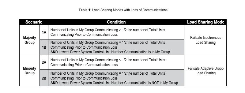
Failsafe Mode occurs when at least one unit on the network loses complete communication with other units on the network. In a ring topology, this would require two breaks (X) in the network. In a star topology, only one break is required. If a loss of communication happens with one, or more units on the network, all units will go into a Failsafe Mode. In Failsafe Mode, all units will fall into one of two groups, Majority or Minority.
Caterpillar’s patented strategy called Failsafe Adaptive Load Sharing Operation intelligently switches units to a control scheme, that enables uninterrupted, stable operation for as long as it takes for full communication to be restored. The communication loss also triggers an alarm that alerts operating personnel to the condition so that repairs can be expedited. Table 1 and Figure 1 illustrate the conditions that determine how to assign a unit to each group. The Cat ECS 200 is used as an example which supports ring topology with Advanced Parallel Control Data Link (APCDL),
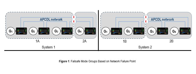
In System 1, The break is between generators 3 and 4. Generators 1, 2, and 3 are still communicating together. Since those three generators make up more than half the total units in the system, they are assigned to the Majority Group. Since generator 4 is in a group by itself that does not make up more than half the total units in the system, it is assigned to a Minority Group.
In System 2, The break is between generators 2 and 3. Generators 1 and 2 are still communicating together. Since those two generators make up exactly half the total units in the system and the generator in the system assigned the lowest number (generator 1) is also in that group, they are assigned to the Majority Group. Since generators 3 and 4 are in a group that make up exactly half the total units in the system and the generator in the system assigned the lowest number (generator 1) is not in that group, they are assigned to a Minority Group.
It is possible for there to be no Majority Group if there are multiple breaks in the communication network. See Figure 2 for an extreme case of this situation.
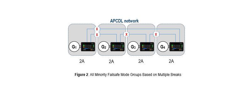
Note: During Failsafe Mode, a Minority Group will not become a Majority Group if more units are added to that Minority Group. A Majority Group might become a Minority Group if enough units are taken out of that Majority Group.
STABILIZING SYSTEM PERFORMANCE
The Failsafe Mode approach using the Cat ECS 200 safely maintains stability through a loss of communication, seamlessly transitioning into failsafe mode with gradual, stable movement to a new equilibrium point. In the case of a ring network configuration, which is optional with Cat ECS 200, the first break in communication has no effect on operation. For a controller in a ring network, that controller will not enter failsafe unless there are two or more breaks in the ring network.
Under this approach, the failsafe mode is triggered when communication messages from one or more Cat ECS 200 units are not received following a specified time interval. The communication loss can result from conditions such as broken wires, improper configuration, power loss to the Ethernet router or hub device, or power loss to a Cat ECS 200 unit.
When communication is lost, control system will enter a safe operating mode that supports simultaneous droop and isochronous modes, depending on how many units are still communicating with each other. The failsafe strategy includes the following features:
- Improves system stability immediately following a network failure by seamlessly switching the units into a Failsafe Mode while continuing to provide load with minimal disruption to the system
- Increases system load capability over standard droop implementation by providing even distribution of loading between units to better serve load during failsafe operation and preventing premature under-loading or over-loading of isochronous units
- Decreases risk of reverse power over standard droop implementation
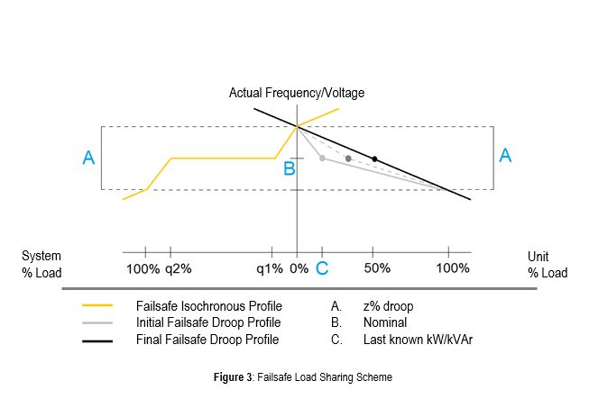
The control system uses knowledge of the network topology to be cautious regarding units that have lost communication. Units in a fragmented or split network will be separated into either a Majority Group or Minority Group. The type of group determines the load sharing mode of the generator sets in those groups. The Failsafe Adaptive Droop and Failsafe Isochronous Load Sharing control profiles are depicted together in Figure 3 below.
Failsafe Droop units are controlled based on adaptive droop curves that converge to a standard droop curve with each successive system load swing. This allows for a controlled migration from the unit’s initial (last known load sharing) load level to a fixed 50% loading.
Failsafe Isochronous units that experience loading outside specified thresholds (q1% and q2%) benefit from the ability of failsafe droop units to provide additional load. This means at extreme (but within ratings) load levels, the failsafe isochronous units avoid premature overloading/underloading and force failsafe droop units to compensate.
Each of the Load Sharing Modes is described in more detail in the following sections.
FAILSAFE ISOCHRONOUS MODE
In general, a generator set operating in isochronous mode maintains constant speed/frequency (voltage), regardless of the load it is supplying. However, Failsafe Isochronous units operate such that speed/frequency (voltage) remain the same for the majority of its load range, but droop speed/frequency (voltage) slightly at extreme load ranges. This is done to prevent premature overloading or underloading and provide more even distribution of loading during failsafe conditions. Outside this isochronous range, aggressive slopes are created until load reaches 100% (or 0%). At these load ranges, the generator set exhibits a resistance to taking on more load (approaching 100% load), and a resistance to dropping more load (approaching 0% load). Outside these ranges, the droop settings apply.
The operating ranges for units in Failsafe Isochronous Load Sharing are shown in Figure 4 and are described below.
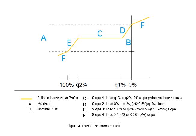
The z% slope is determined by the values programmed for the droop percentages and q1% and q2%.
For Real Load Sharing, the Generator Real Load Sharing Minimum Deviation Percentage setpoint determines the q1% point and the Generator Real Load Sharing Maximum Deviation Percentage setpoint determines the q2% point.
For Reactive Load Sharing, the Generator Reactive Load Sharing Minimum Deviation Percentage setpoint determines the q1% point and the Generator Reactive Load Sharing Maximum Deviation Percentage setpoint determines the q2% point.
FAILSAFE DROOP MODE
In general, generator sets operating in droop mode decrease speed/frequency (voltage) proportionally to load. That is, as the load increases the speed/frequency (voltage) decreases. With the standard droop implementation control scheme a generator set will always produce the same power output at a particular speed/frequency (voltage). However, Failsafe Adaptive Droop units operate such that the last known power output at the time of loss of communications remains constant to avoid instability and any sudden load transfer. Over time, however, the power output level is migrated to a more desired level with each successive load swing. This controlled migration results in a more even distribution of loading between droop units and isochronous units. The process by which this migration is accomplished in Failsafe Adaptive Droop is shown in Figure 5 and described below.
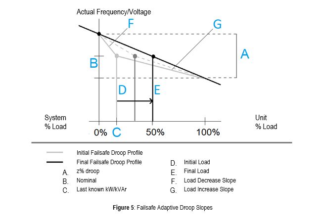
At the time of communications loss, a failsafe adaptive droop unit will run at an operating point defined as nominal frequency at the last known % kW (kVAr) of that individual generator set. From this operating point, a droop characteristic made up of two (2) droop slopes is defined:
Load Decrease Slopes:
- Calculated from nominal actual frequency (voltage) at the last known kW (kVAr) prior to losing communications to nominal actual frequency, plus (z/2)*frequency at 0% kW (kVAr).
Load Increase Slopes:
- Calculated from nominal actual frequency (voltage) at lthe ast known kW (kVAr) prior to losing communications to nominal actual frequency, minus (z/2)* frequency at 100 % kW (kVAr).
The droop unit’s frequency (voltage) tracks up the Load Decrease Slope and down the Load Increase Slope as droop unit % kW (kVAr) varies. The Load Decrease Slope and Load Increase Slope are re-calculated at each movement up and down. Therefore, as the droop unit’s load varies, the Load Decrease Slope and Load Increase Slope converge to a standard droop slope with 50% load at nominal frequency (voltage). A droop unit’s kVAr and voltage droop operation is analogous to the kW and frequency operation described above.
Note: If a failsafe adaptive droop unit’s % load drops below 0% load or rises above 100% load, the programmed droop is implemented.
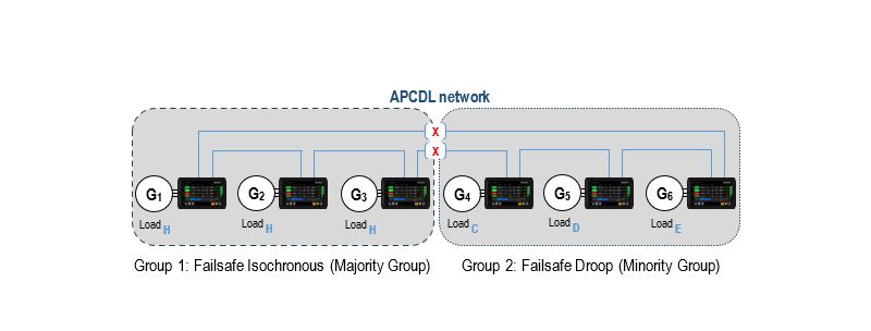
FAILSAFE LOAD SHARING EXAMPLE
In this example, six units are load sharing when communication is lost between two groups of three units each (Group 1 = units 1, 2, 3, and Group 2 = units 4, 5, 6). Group 1 will go to Failsafe Isochronous mode (Majority Group), while Group 2 goes to Failsafe Droop mode (Minority Group). The three Failsafe Droop units each have different loading levels at the time of communications loss. The three Failsafe Isochronous units will be operating at a point defined as nominal frequency at the last known % load of that individual generator set. Figure 6 represents an example starting point for all 3 droop units.

1. Loss of Communications
Majority and Minority Groups are established. Units in the Majority Group can accept variable load while the Minority Group units have their individual load levels fixed. Minority Group units determine Load Decrease and Load Increase slopes.
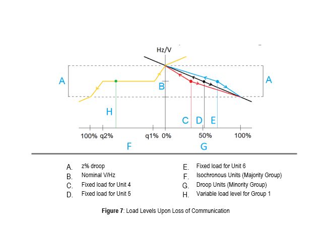
2. Failsafe Adaptive Droop and Failsafe Isochronous Load Sharing
The units in Group 2 (Failsafe Droop mode) will maintain a fixed power output as system load changes. The units in Group 1 (Failsafe Isochronous mode) will adjust their power output as load changes within the q1% and q2% points. See Figure 7.
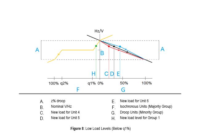
3. Failsafe Adaptive Droop Operation Below q1% (Low Load Levels)
When the load has been reduced to the point where Group 1 is below the q1% point, the Failsafe Isochronous units exhibit resistance to unloading. As the Failsafe Isochronous units unload less freely, the bus frequency/voltage increases, and the Failsafe Droop units track upward on their respective Load Decrease Slopes to begin to unload (since system voltage and frequency are consistent against all units on the bus). During this time, the Load Increase Slopes are recalculated creating a new droop trajectory back towards 100% load. The Failsafe Droop units will follow this new trajectory the next time system load increases. See Figure 8.
Note: The Failsafe Adaptive Droop units are closer to a matched load than the initial (last known) load level at the time of communications loss.
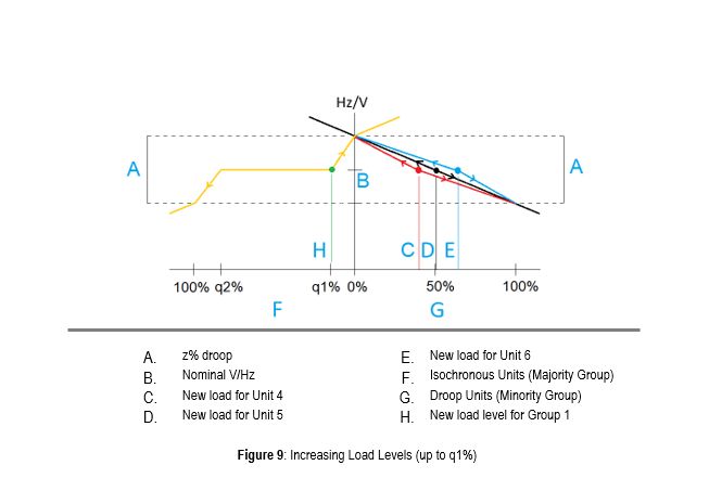
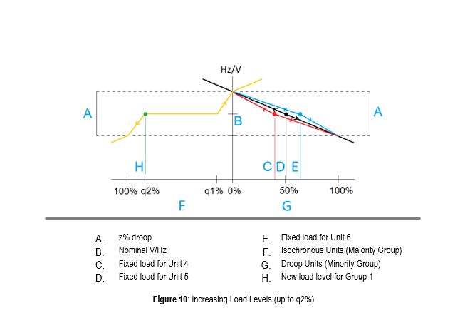
4. Load Increases From 0% to q1%, Then From q1% to q2%
As load increases towards q1%, the Failsafe Droop sets now have new droop trajectories toward 100% and 0%. Notice that the Failsafe Droop sets are closer to a matched % load than previously. As load increases above q1%, the Failsafe Isochronous set takes on all load up to the q2% point. See Figures 9 and 10.
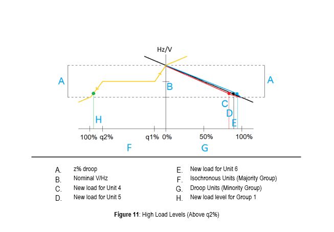
5. Failsafe Adaptive Droop Operation Above q2% (High Load Levels)
As load increases above q2%, the Failsafe Isochronous units exhibit resistance to overloading. As the Failsafe Isochronous unit resist taking on load, bus frequency/voltage decreases, and the Failsafe Droop units track downward on their respective Load Increase Slopes to take on more load (since system voltage and frequency are consistent against all units on the bus). During this time the Load Decrease Slopes are recalculated creating a new droop trajectory, back towards 0% load. The Failsafe Droop units will follow this new trajectory the next time system load decreases. See Figure 11.
Note: The Failsafe Adaptive Droop units are closer to a matched load than the initial (last known) load level at the time of communications loss.
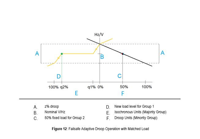
6. Failsafe Adaptive Droop Operation with Matched Load
Over time, as system load swings dictate, the recalculation of the Load Increase Slope and Load Decrease Slope result in all units migrating to the same 50% loading point at nominal frequency on a standard droop curve. In practice, load variations may cause transients that result in the migration of the droop units to the 50% loading point without system loading in the q1% or q2% ranges. This is not a concern since droop units migrating to matching load in a controlled way is a preferred operating point.
In general, if all generator sets in a droop system have the same droop setting, they will each share load proportionally. A benefit of Failsafe Adaptive Droop is that even though the percent load on each droop unit is initially disproportionate to maintain stability, over time, as system load changes, the adaptive droop results in all droop units sharing load proportionally with the same droop settings. See Figure 12.
RETURNING TO NORMAL
The Failsafe Isochronous Load Sharing and Failsafe Adaptive Droop modes are intended for failsafe operation only and not for normal operation over long periods. While a generator system operating in failsafe mode will serve system load adequately, normal load sharing is a more robust and stable operating mode.
After the failsafe modes are activated, the system requires investigation. An alarm indicates when communication loss has occurred. This can take the form of a flashing light, an audible signal, a text message or call to operators’ smart phones, or some combination of these, depending on how the alarm system is configured. On receipt of the alarm, proper troubleshooting steps should be taken as soon as possible to return the system to normal operation.
The load sharing protocol is designed to enable transition to and from the failsafe modes as seamlessly as possible, although that cannot be absolutely guaranteed. Changes to load sharing-gains and system loading significantly affect the ability to transition between the failsafe and normal operating modes without disturbance.
To exit Failsafe Mode, any of the following conditions are necessary:
- The system agrees that the expected units before entering Failsafe Mode are all now communicating on the network
- Manual reset of the Expected Number of Units from the display
SUMMARY
The Failsafe Adaptive Load Sharing Operation control strategy offers a unique advantage in providing stability even after a failure in the communication network of a multiple-generator-set power system. The Cat ECS 200 using Failsafe Adaptive Load Sharing Operation is an example of such a control scheme to enable uninterrupted, stable operation for as long as it takes for full communications to be restored.