
If you already have an existing account with another Cat App, you can use the same account to sign in here
One Account. All of Cat.
Your Caterpillar account is the single account you use to log in to select services and applications we offer. Shop for parts and machines online, manage your fleet, go mobile, and more.
Account Information
Site Settings
Security
Remote Start Circuit Integrity National Electric Code (NEC) 2017 Articles 695.14(F) and 700.10(D)(3)
Anis Ahmed
Electric Power, Caterpillar Inc.
SUMMARY
This paper discusses requirements from National Electric Code (NEC) 2017 Articles 695.14 (F) Fire Pumps and 700.10 (D)(3) Emergency Systems, Tentative Interim Amendment (TIA 17-17) and Caterpillar’s solution to satisfy the NEC code.
The language of the NEC codes and associated Tentative Interim Amendments are as follows:
Code Language – NEC 2017 Article 695.14 (F) – Fire Pumps1
Generator Control Panel Wiring Methods. Control conductors installed between the fire pump power transfer switch and the standby generator suppling the fire pump during the power loss shall be kept entirely independent of all other wiring. The integrity of the generator control wiring shall be continuously monitored. Loss of integrity of the remote start circuit(s) shall initiate visual and audible annunciation of generator malfunction at the generator local and remote annunciator(s) and start the generator(s).
Tentative Interim Amendment (TIA 17-17). Control conductors installed between the fire pump power transfer switch and the standby generator suppling the fire pump during the power loss shall be kept entirely independent of all other wiring. The integrity of the generator remote start circuit shall be monitored for broken, disconnected or shorted wires. Loss of integrity—start the generator(s).
Code Language – NEC 2017 Article 700.10 (D) (3) – Emergency Systems1
Generator Control Panel Wiring Methods. Control conductors installed between the transfer equipment and the emergency generator shall be kept entirely independent of all other wiring and shall meet the conditions 700.10 (D) (1). The integrity of generator control wiring shall be continuously monitored. Loss of integrity of the remote start circuit(s) shall initiate visual and audible annunciation of generator malfunction at the generator local and remote annunciator(s) and start the generator(s).
Tentative Interim Amendment (TIA 17-17). Control conductors installed between the transfer equipment and the emergency generator shall be kept entirely independent of all other wiring and shall meet the conditions 700.10 (D) (1). The integrity of the generator remote start circuit shall be monitored for broken, disconnected or shorted wires. Loss of integrity—start the generator(s).
Note1: Information replicated from the NFPA 70 2017 Edition National Electric Code. Reference Article “695.14 (F),” “700.10(D)(3)” and Tentative Interim Amendment “TIA 17-17 SC 18-8-22 / TIA Log #1357.”
Tentative Interim Amendments are in effect for these codes until the next release of the NEC code in 2020, which provides specific updates to these articles. These amendments remove the complexity of the code for its intended use by:
- Removing the requirement of Full Controls Circuit Integrity and limiting to only Remote Start Circuit Integrity;
- Removing the requirement of Continuous Monitoring of the Remote Start Circuit; and
- Removing the requirement of Visual and Audible Annunciation of the Remote Start Circuit (disconnected, open or short).
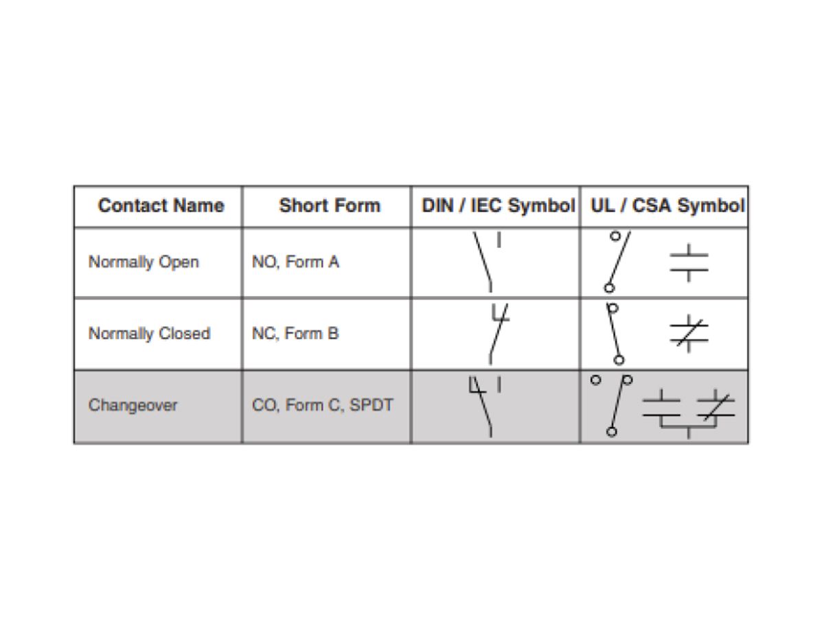
Figure 1: Form A, B and C-Relays. Remote Start Signal Integrity requires Form C-Relay.
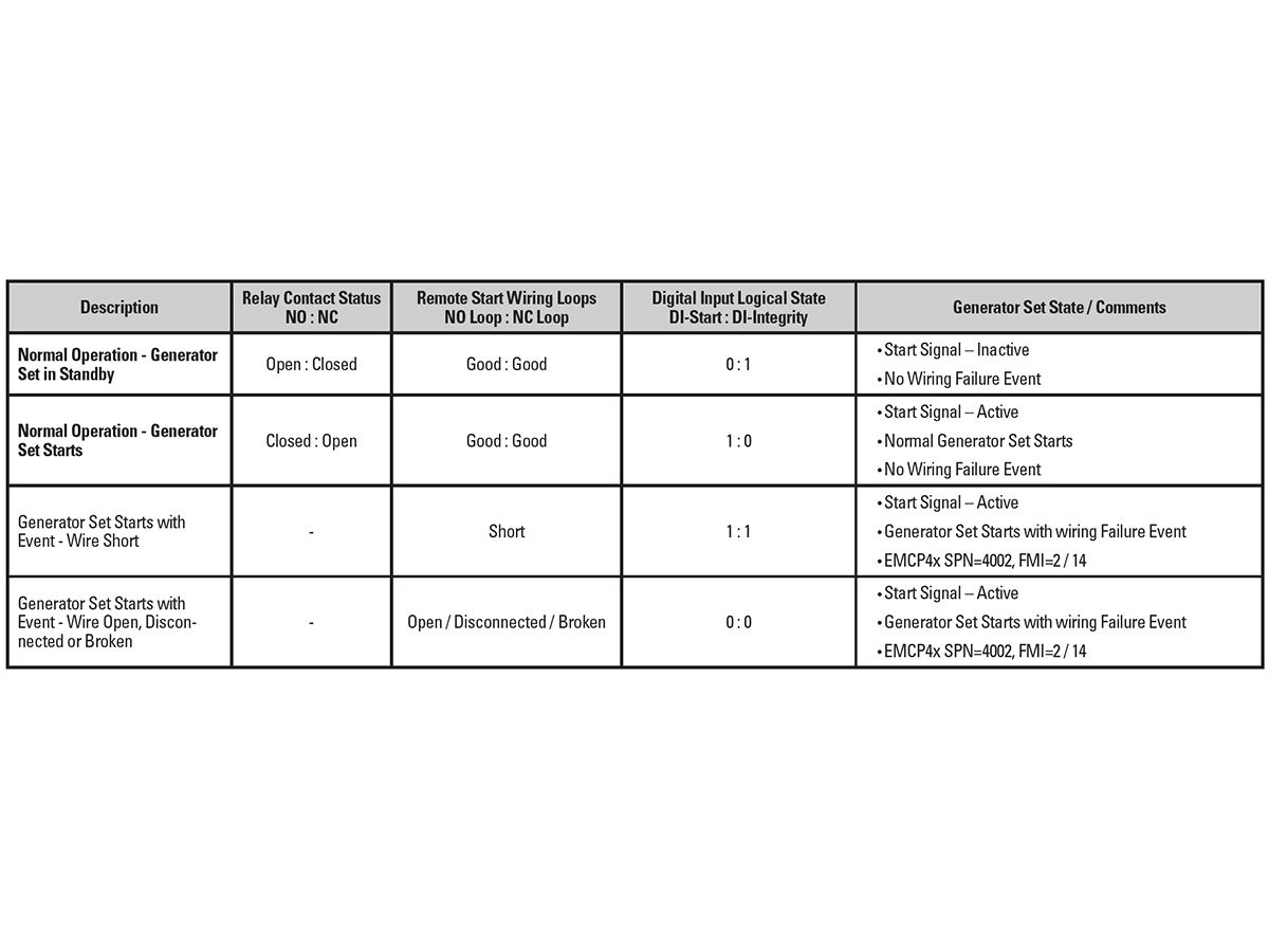
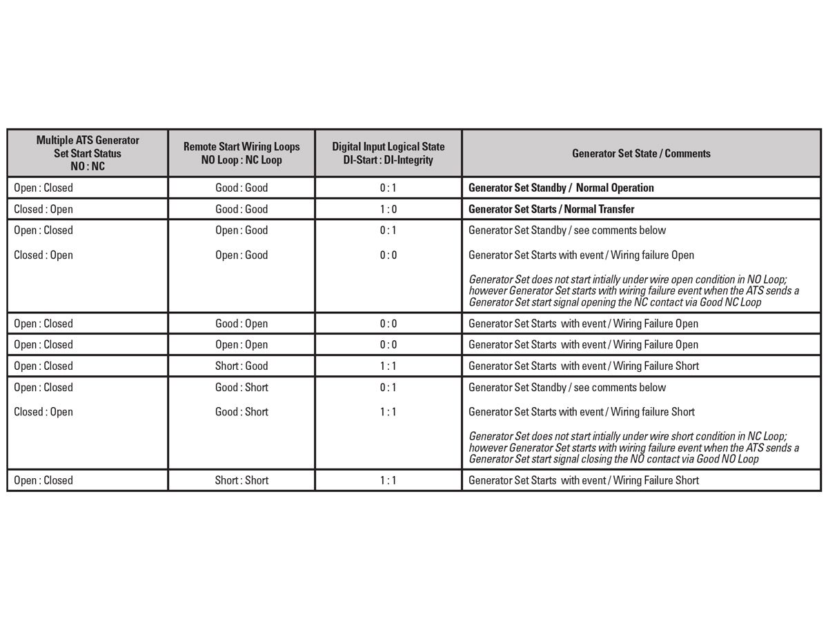
Table 1: Wiring Integrity Truth Table
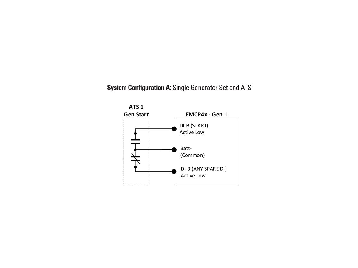
Figure 2: System Configuration A – Single Generator Set and ATS
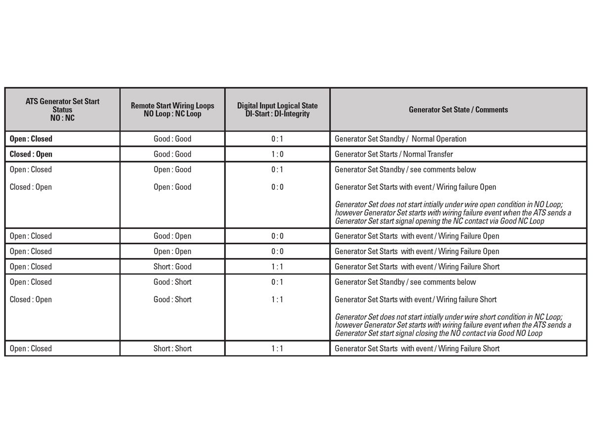
Chart 2
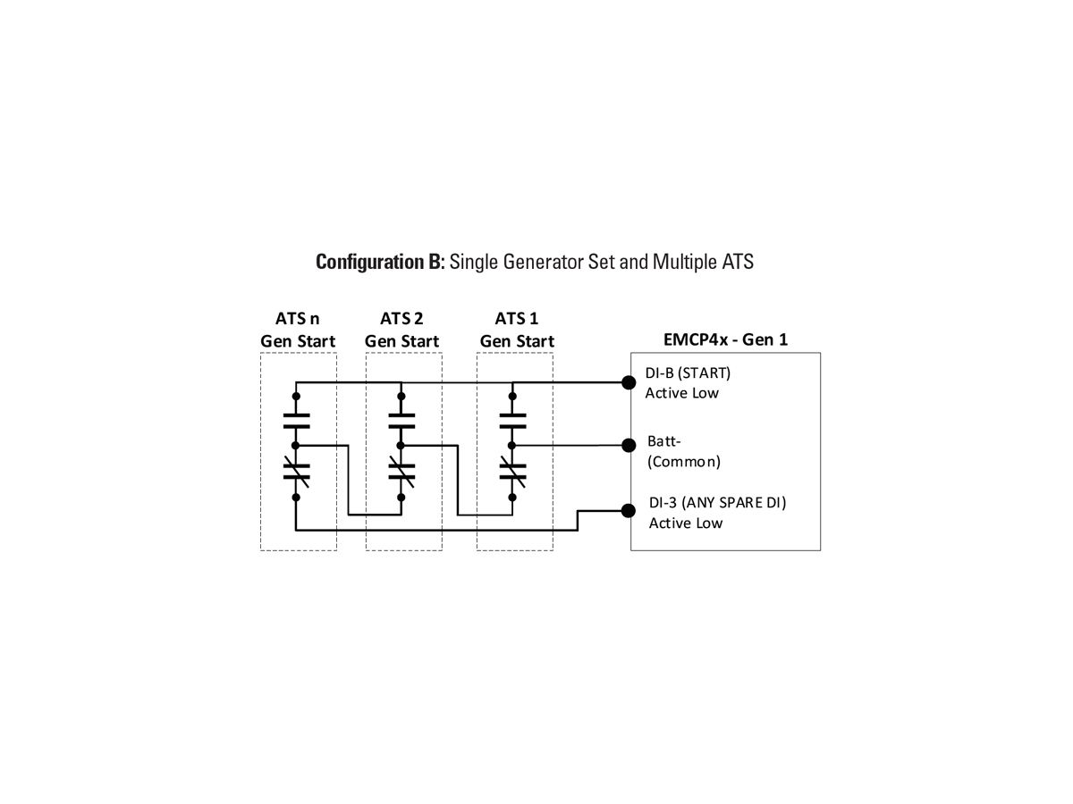
Figure 3: System Configuration B – Single Generator Set and Multiple ATS
To simplify the truth table for readability purposes NO and NC contacts above are cumulatively representing multiple ATS.
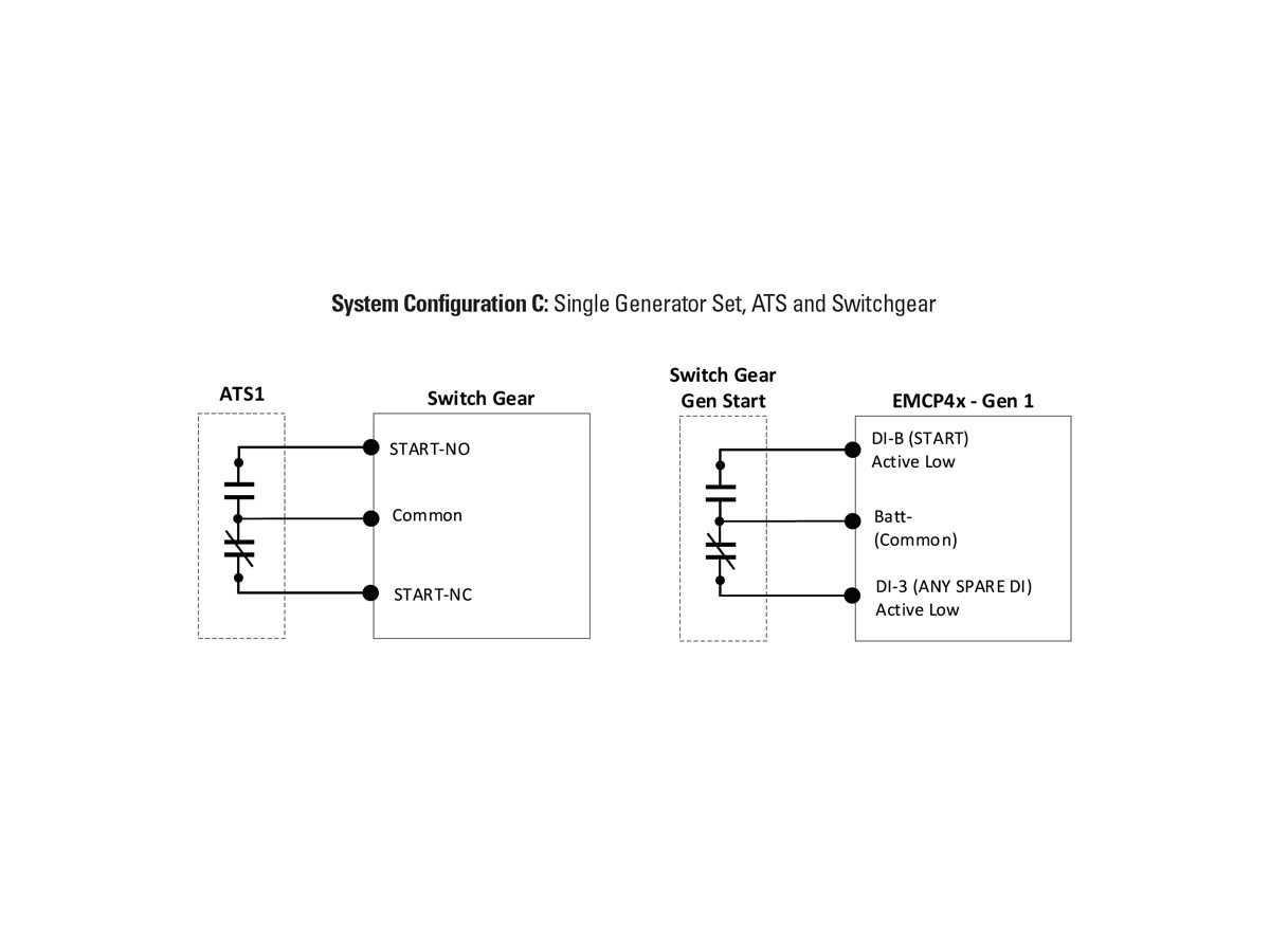
Figure 4: System Configuration C – Single Generator Set, ATS and Switchgear
Caterpillar’s Interpretation, Recommendation and Solution
To meet NEC 2017 Article 695.14 (F) Fire Pumps and 700.10 (D)(3) Emergency Systems per the Tentative Interim Amendment as explained in previous section, two items need to be addressed: isolated remote start circuit; and, the integrity of the remote start circuit for disconnected, broken or short wire.
For all the potential system configurations, wiring isolation can be achieved by running the remote start signal wires in a separate conduit or run as accepted by your local AHJ (Authority Having Jurisdiction).
Circuit integrity for disconnected, open or short remote start wire can be achieved by using a form C-Relay and an additional input for integrity beside the dedicated remote start digital input. Depending on the system configurations explained below for Cat® EMCP 4x generator set controllers and switchgear, each may require a separate set of form C-Relay and a digital input for their corresponding wiring loops.
The following paragraphs establish a foundation by providing a basic understanding of terms, conventions, requirements and a truth table.
- NO = Normally Open, NC = Normally Closed
- NO Loop is the wiring loop from common going through the NO contacts
- NC Loop is the wiring loop from common going through the NC contacts
- Changeover Form C - Relay/Contacts - single pole double throw (SPDT) used for the integrity circuit
- Wiring Integrity Truth Table
The following controllers, software and Cat® ET are required for a generator set equipped with a Cat EMCP 4x controller:
- Cat EMCP 4.2B, 4.3 or 4.4 controller with Prod 4.8 software or later
- Cat EMCP 4.2 controller with Prod 4.4.3 software or later
- 2017B or later Cat ET is required, otherwise program with display
- Cat EMCP 4x digital “integrity” input active state must be configured as “active low”
SYSTEM CONFIGURATIONS
While the remote circuit isolation requirement is common to all configurations, there are differences in remote start circuit diagrams depending on the system configurations described below.
Even though the remote start circuit diagrams differ, the fundamental aspect of the truth tables remains the same across these various system configurations explained in the sections below.
These various system configurations require circuit diagrams and truth tables to achieve remote start circuit integrity to satisfy NEC 2017 code:
A. Single Generator Set and ATS (see images, Figure 2)
B. Single Generator Set and Multiple ATS (see images, Figure 3)
C. Single Generator Set, ATS, and Switchgear (see images, Figure 4)
D. Multiple Generator Sets, Multiple ATS, and Switchgear (see images, Figure 5)
Note: When wiring failure happens in the Switchgear-ATS wiring loop, the event will be generated and displayed at the Switchgear. However, if the wiring failure happens in ATS-Generator Set or Switchgear-Generator Set wiring loop, the event will be generated and displayed at the Generator Set. Regardless of any wiring loop failure, the ultimate result will be a “Generator Set Start” with start wiring failure event.
Remote Start Wiring Integrity Configuration for Cat EMCP 4x Generator Set Controller
Cat EMCP 4x provides two parameters for Integrity Digital Input that can be configured for any available digital input. ENG REMOTE START (INVERTED) is used for single and GRP REMOTE START (INVERTED) is used for multiple ATS, shown in Figure 6 with associated wiring failure events and shown in Figures 7 and 8.
Furthermore, these events can be annunciated on a custom annunciator. (Figure 9)
CONCLUSION
With a good understanding of the NEC code requirement, the recommendation and solution provided in this white paper makes it comfortable and straightforward to adapt and comply with the NEC code, while the final authority to approve is AHJ.
Disclaimer: Copyright 2017, National Fire Protection Agency, “NFPA 70: National Electrical Code, 2017 Edition.” Regarding the quoted material from NFPA 70: This reprinted material is not the complete and official position of the NFPA on the reference subject, which is represented solely by the standard in its entirety.